60 Second MSI/SSI Counter
Problem Statement
In this project you will get to demonstrate both the MSI and SSI asynchronous counter by creating a Sixty Second counter. The counter will have to count from 00-to-60 and reset back at 00 once you press the reset button . You will simulate and build the Sixty Second counter.
Constraints
-Must have both SSI and MSI
-Must use the IC chips 74LS48 74LS93 74LS74 74LS76
- Must be simulated and build.
- Must use common cathode SSDs
-Must use the IC chips 74LS48 74LS93 74LS74 74LS76
- Must be simulated and build.
- Must use common cathode SSDs
Calculations
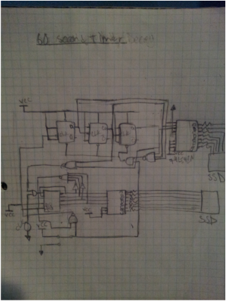
The first thing I had to do was to sketch the design for the Sixty Second counter on a piece of paper. This sketch should theoretically work on multisim.
Documentation
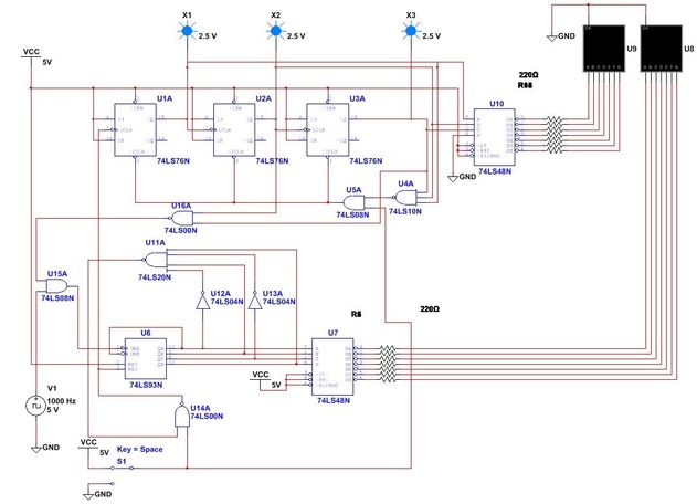
This is the Multisim design that I created and it worked how it was suppose to. It counts from 00-60 and resets once I press the push button.
Due to the amount of time that I have left, I have decided to program the circuit into the DLB. This is the PLD version of my 00-60 second counter.
PLD
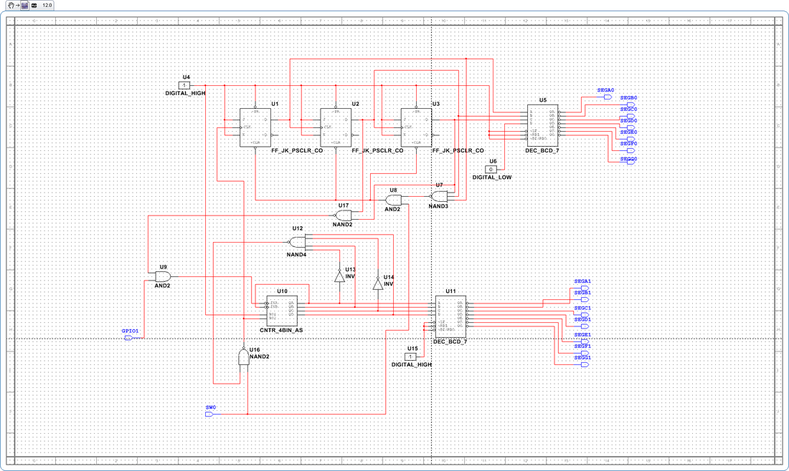
Final Design
00-60(DLB)
Reflection
I really learned much from this project. The part that would have been the most difficult would have been physically bread boarding this design , but due to the time limit I had to digitally program my design into the DLB. As you can see in my Multisim design, The counter contains two different counters, one that uses MSI logic and counts from 0-9 and resets at 0, and another that uses SSI and counts from 0-6 and restarts at 0. The way the MSI counter works is that when the count can only reach a max count of 10. This is cause we have two inverters which only let the binary count reach 1010 which is 10.That count will go through a 4-input NAND gate and we will get a 1 but this will turn into a 0 since input will go through a 2-input NAND gate with the SPDS switch when the switch is at 1, and this 1 will go to the R02 input on the 74LS93. Both R01 and R02 are both wired to VCC which will make the whole MSI circuit reset 0. For the SSI part of the project I used three flip flops cause this will give us the max binary count of 2^3 which is 8 or 0-6 and that is what we want. The way the SSI circuit works is that every time the MSI output resets to 0 you will get a 1 from the 4 input NAND gate but this will be inverted back to a zero and the back to a 1 which will give you a pulse. This means that for every count cycle the MSI circuit makes you will only get one from the SSI. To make the count stop at 60 we have to take the 110 binary output from the SSI logic and run it through a 2-input NAND gate, so whenever the outputs C and B are 1’s, they will be turned into a 0. This output and the output from clock will be wired into an AND gate and the out put will be wired to INA on the 74LS93 which makes the count stop at sixty until you reset it with the switch. After that it was easy to DLB my design. I just switched the clock and the switch to GPIOs and wired them externally and the SSD were on the board. Since we have already learned about the debouncer everything worked fine and the circuit didn't bounce.
