Copy Jam Detector
As the paper passes through a copy machine, three sensors monitor its sensors monitor its path. If two of the three sensors are turned on it will register a jam(they must be next to each other in order for there to be a jam). When a paper jam occurs, an LED indicator light will turn on and a buzzer will sound. The LED indicator will go off as soon as the jam is cleared.The buzzer should continue to sound until a Clear button is
pressed.This last condition requires that the output controlling the buzzer be latched with a flip-flop.
pressed.This last condition requires that the output controlling the buzzer be latched with a flip-flop.
Problem Statement
Design a Paper Jam Detector circuit that meets the design specifications detailed and program the PLD design into the digital logic board.Verify that the circuit is working as designed.
Constraints
- Design a circuit that uses the flip flop
- Program it into the DLB
- Must be checked
- Program it into the DLB
- Must be checked
Calculations
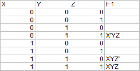
Truth Table
This was the truth table that I made based on my design. Each one of the letters XYZ represents each one of the jam detectors.
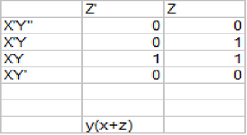
K-Mapping
This was the K-mapping I did form my truth table. It was pretty easy to get the1's cause the paper jam only occurred when two adjacent(next to each other) jam detectors registered a jam. This only happened three times, XYZ' X'YZ, and XYZ. After that I got my simplified minterm that should work accordingly on multisim once the flip flop is added.
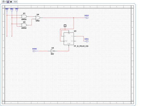
Documentation
This is the PLD design of my copy jam detector circuit. It contains the asynchronous clock and the AOI logic circuit that I design.
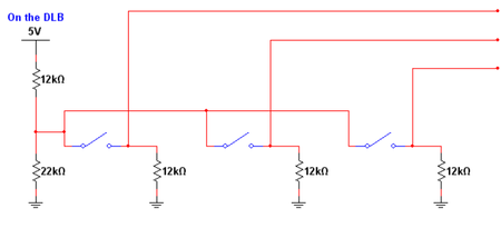
This circuit was given to us to show us how to breadboard(wire) it on the DLB once we programmed the jam circuit into it.
Final Design
This is a video of the final design programed into the digital logic board as you can see the LEDs stay lit only when two adjacent jam detectors register a jam. When I press the Clear button all the LEDs go back to 0 as it is suppose to.
Reflection
This project was pretty easy up until the wiring. The truth table was pretty easy to make cause we usually work with three outputs(xyz) and the K mapping was easy cause we only had three possible minterms with an outcome of one so it was pretty easy to simplify. I really had no problem building the circuit, cause every thing was pretty straight forward and Mr. Wemp had taught us how to wire the flip flops so all I had to do was attach my AOI circuit with the flip flop and connect a BTN0 to clear and two LEDs . After that I programmed it into my DLB and this was were I got stuck. When I first wired the circuit i thought that i had to to connect my VCC to the 12k resistor and then connect the GND and then to the 22k and join those to like it was shown on the circuit that was given to us. I actually had to wire them seperatly and connect each one to each of the jam detectors.This took me a while to realize but once i got it it worked fine. Also I think i shoulda done this project earlier cuz the problem stated that we needed 12k resistors but i couldnt find any so i replaced it with a 10k resistor. I was worried that the resistor would fry but luckly it worked. This project was really fun cause sometimes my printer jams and it pushes the paper out and it is pretty cool that i know how it works now.I hope that on the next project we do more with the flip flops and make another type of project that is similar to this one.
