SSI Synchronous Counter
Problem Statement
Simulate and analyze two 3-bit synchronous counters. The first counter will be a synchronous 3 bit binary up counter with JK flip flops that will count from 0-7.It incorporates a SPDT switch that you must toggle from VCC to GND and see what happens. The other circuit we will test is the same circuit but it is modified to count up from 0-5 by taking out the SPDT and putting in a 3 input NAND gate. We will also analyze and modify the circuit to count down instead of up.
Constraints
-build both circuits in multisim
-mod the second circuit to count down
-use the HEX display
-mod the second circuit to count down
-use the HEX display
Calculations
All flip-flops are simultaneously clocked by an external clock. This means that all the flip flops will pulse at the same time and this is why they are synchronized.I think that this will be the key to chainging the count and which way the counter counts.
Documentation
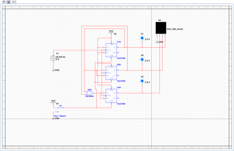
Synchronous 3-Bit Binary Up Counter
This is the Synchronous 3-Bit Binary Up Counter. It counts from(0-7) and restarts. As you can the SPDT is outputting a 0 to clear and preset is connected to vcc(0) so they will not affect the circuit. The way the circuit works is simple. The first flip flop has J and K wired to 1 so Q0 will pulse on the falling edge of the clock cause when J and K are 1 it toggles Q to the opposite. The second flip flop gets its J and K inputs from Q0 so it when will pulse every time Q0 out puts a 0 which splits the pulse in half. The last flip flop gets its J and K outputs from the NAND gate that is connected to Q0 and Q1.The only two times it pulses is when both Q1 and Q2 are 1 which will make Q2 stay at 1 and the counter continues to count 3,4,5,6 and at 7 Q0 and Q1 get an input of 0 and Q2s J and K inputs will be at zero so Q2 will also be 0 which will restart the count.
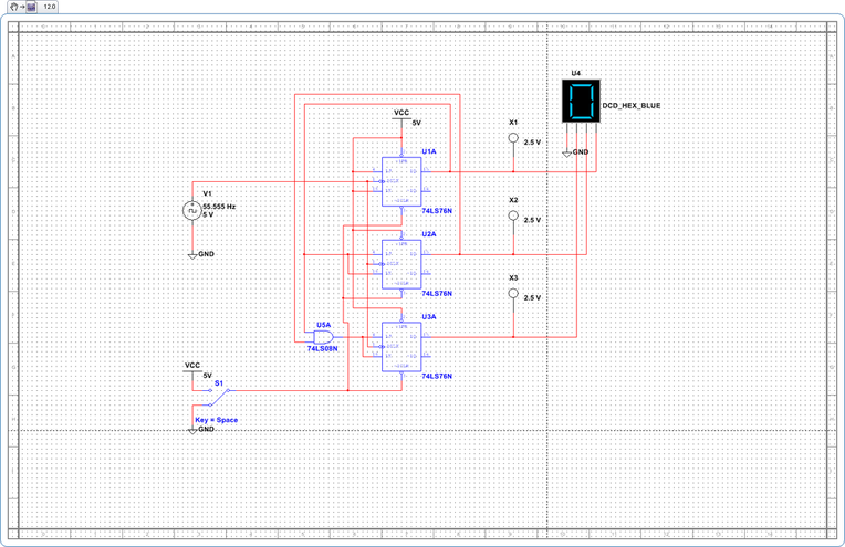
Synchronous 3-Bit Binary Up Counter(SPDT to GND)
This is the Synchronous 3 Bit Binary Up Counter with the SPDT toggled to GND. When I tried to toggle the SPDT while the video was recording it, the program would not let me so below is what the circuit looks like when the SPDT is toggled to GND. What happens is very simple, every time the SPDT is toggled to GND it outputs a 0 to clear on all of the JK flip flops. As you can see in the circuit all of the presets on the JK flip flops are connected to vcc, so when we toggle the SPDT to GND they will all have a preset(1) and clear(0) which makes all Q outputs 0 and 000=0 until the SPDT is toggled back to 0.
Synchronous 3-Bit Binary Up Counter Vid
This is the Synchronous 3-Bit Binary Up Counter video. It works according to the design given to us ,which was that it had to count from 0-7. As I stated above I could not toggle the SPDT during the recoding.
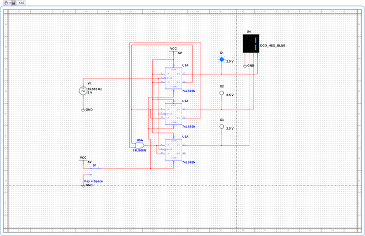
Synchronous 3 Bit Binary Down Counter
This is the Synchronous 3 Bit Binary Down Counter that we had to make by modifying the the up counter.The way we did this took almost no time. All I did was move the NAND inputs (Q0 & Q1) to the opposite(Q0' and Q') and it started counting back. The reason this happens is that when the clock pulses in the NAND gate gets its outputs from Q' so instead of sendinding a 1 to JK it sends a 1 wich makes the second flip flops Q1 output be a 1,and the NAND gate has a combination of 00 so the bottom flipflops JK dont affect the circuit wich means the bottom clock gives out a 1.By connecting the Q0,Q1, and Q2 to the HEX display we start the circuit off at 111 and that is 7 in the HEX Display.The NAND gate has Q' inputs wich means it will do the opposite of what it did in the up counter,hence counting backwards.
Synchronous 3 Bit Binary Down Counter Vid
This is the synchronous 3 bit binary down counter.It counts down from 7-0 and then restarts as it shouold.
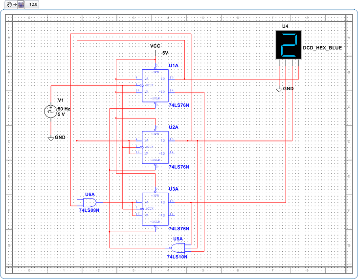
Binary MOD 6 Binary Up Counter
This is the Binary MOD 6 up Counter it counts from 0-5. Unlike the Fist counter this counter does not incorporate a SPDT so it will always be on. Instead it that it has a three input NAND gate and this is the key to make the counter count from 5-0.the max count is 5 which happens when Q0 is a 1, Q1 is a 0, and Q2 is a 1(101=5).When the next pulse (011) happens the three input NAND gate gets a 1 from Q0', a 1 from Q1, and another 1 from Q2which is 111 and this gets inverted into 000. The NAND gate is connected to the 3 Clears of each one of the flip so all the clears are 0 and since preset is wired to vcc, they are all 1s. All the Qs go to 000 and the circuit restarts again.
Synchronous MOD 6 Binary Up Counter Vid
This is the Synchronous MOD 6 Binary Up Counter video. It counts from 0-5 and then repeats the count as it should.
Conclusion
1. What do you think are the advantages of Synchronous Counters over Asynchronous Counters?
The main advantage of using Synchronous Counters is that their is no ripple effect unlike the Synchronous.Right now we are building small circuits so it doesnt matter but when working with advanced circuits that require really high speeds the Synchronous counter is the way to go.The reason is that the Asynchronous counter is at a disadvantage is cause its pulses are unsynchronized, and at high sppeds this will cause errors with the circuit, However SYnchronous counterss keep the pulses synchronized hence their will be no error.
2. Do Asynchronous Counters have any advantages?
The advantage of the Asynchronous Counter is that the circuit is easier to build.This makes the work easier but thats about it.If you are making a circuit with a really slow pulse then Asynchronous counters are the way to go.
3. What changes must be made to a 3 Bit Counter to make it a 4 Bit Counter?
To make a Synchronous 3 Bit counter turn into a 4 Bit you have to add another flip flop in you would wire the 3rd flip flop on to the 4th just as you wired the 2nd to the 3rd.Also you would add a 3 input AND gate to the circuit connect the outputs of Q0,Q1, and Q2 to the inputs of the gate and last wire the 3 input NAND gate's output to JK this would encorporate the 4th gates pulse into the time line and hence makke a 4Bit Counter.
