Introduction to Flip-Flops
Positive Edge and Negative Edge Triggered Clocks
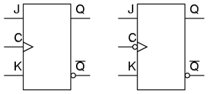
Before we get into flip flops you must know that there are two different types of clocks, positive edge and negative edge triggered. The difference between the two is that the positive edge triggered clocks(right) will pulse when there is a rising edge(1) and a negative edge triggered(left) will pulse when there is a falling edge(0) every thing else stays and keeps on working the same.
D Flip Flops
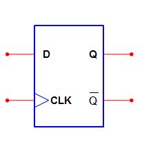
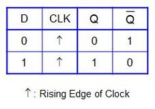
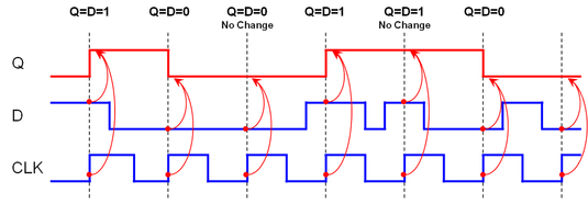
This is the most basic flip flop. The D (data) input is the synchronous input.The D flip-flop captures the value of the D-input at a definite portion of the clock cycle such as the rising edge of the clock(1). That captured value becomes the Q output and Q' is the opposite.When the clock is at a falling edge(0) the output Q does not change. The chart below shows how D overrides Q when the clock is active, in this case at rising edges.
This is a timing example of a D Flip Flop. It works accordingly to the chart above
JK Flip Flop
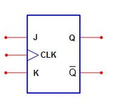
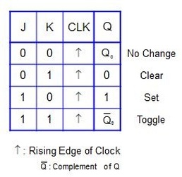
This is a JK Flip Flop. As you can see the Dee input has been replaced with a J and K input hence the name JK flip flop. This flip flop is a bit different but it is basically the same concept. The when the clock is active it must check J and K. Below are all the possible combinations that will determine what Q is. Obviously when both J and K are inactive Q will not change. When K is active(1) and J is inactive (0) Q will clear witch means it will go back to 0. When K is inactive and J is active Q will set witch means it will go to 1 and. Last when both JK are active Q will toggle witch means Q will switch to the opposite of what it currently is.
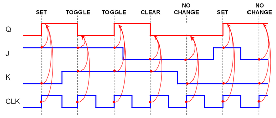
This is a timing example of a JK Flip Flop. It works accordingly to the chart above
Asynchronous Inputs
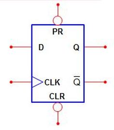
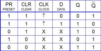
Asynchronous Inputs are just two inputs(preset and clear) that we can add to the previous flip flops we learned about, on top you see a D flip flop with asynchronous inputs . These inputs are very important they decide Q no matter the clock pulse, or any other inputs. You must first check preset and clear before any thing else when they are both active you just treat the flip flop as a normal flip flop either JK or D. When preset is inactive(0) and clear is active(1) Q automatically turns to a one no matter what the clock, data, or J and K are. When preset is active(1) and clear is inactive(0) Q becomes 1 no matter the other flip flops. And last if both clear and preset are inactive Q would be 1 but so would Q' and this is a impossible situation so it really is irrelevant. The chart below shows all the possible out comes.
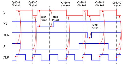
This is a timing example of a D Flip Flop with Asynchronous inputs. It works according to the table above.
J/K Divide By-Two Circuit
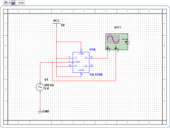
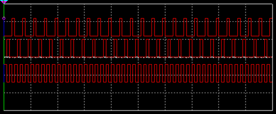
This is the JK divide by two circuit it contains a Asynchronous JK flip flop and a voltage clock and the clock input is negative edge triggered. As you can see preset and clear are both wired to VCC(1) so they will not interfere with the JK flip flop. Both J and K are wired to VCC and as I showed you on the chart when both J and K are 1 it causes Q to toggle hence half of the inputs are transmitted and it divides the data by two. To prove this I connected an oscilloscope to the clock pulse and to the new clock pulse(Q) and ran my analysis. As you can see on the timing chart below the pulse going into input A is half of what is going into input B the original clock.
Non-Overlapping Signal Generator
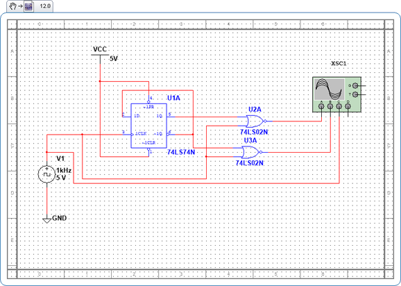
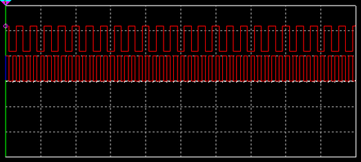
This is the non over lapping signal generator. It has a voltage clock and a Asyncronous D flip flop that has a positive edge triggered clock. The clock, Q, and Q' are wired up to two NOR gates and these along with the original clock pulse are wired to the oscilloscope. So this circuit is pretty much the same as the other one. Both preset and clear are wired to VCC and like I stated on the chart when preset and clear have power(1) they do not interfere with the circuit. By wiring D to Q' we can replicate the effect that the divide by two circuit had on the pulse. When we input 1 into D, Q must turn into a 1 but Q' must be the opposite(0) but since Q' is wired to D this makes D, 0 and then D must be 0 and Q' is one so it creates a cycle that divides the pulse in half. As we can see in the timing chart below Input B has the same pulse as Input A but it pulses in between A. This is caused by the wiring of the two NOR gates .The first NOR gate is wired up to Q and the second NOR gate is wired up to the clock and Q'.Q will get the first pulse and Q' will get a pulse after that, and since the first NOR gate is wired to Q it will pulse first and then the second NOR will pulse. This is how the B input pulses in between the A Input. I think the circuit is called non over lapping cause neither of the circuits(A and B) pulse at the same time.