Date of Birth
Problem Statment
Use your birthday date to design a circuit that will display your date of birth(mm/dd/yy) on a single seven-segment display. Admittedly, this design does not have any real practical application, but is a fun exercise that will bring together all of the design techniques that you have learned in this lesson.In your digital electronics class of 20, there is a 6.8% probability that two of you share the same date of birth.This means that your project will be unique unless you have the birthday as a classmate.
What is a seven Segment Display..
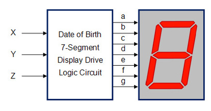
A seven segment display is basically a group of 7 LEDs(some include decimal points).Each segment is labled A-G as shown above and by making certain segments go off(0) and others go on(1) you can create many diffrent characters such as letters and numbers.Seven segment displays are available in two diffrent configurations,Common Cathode(CC) and Common Anode(CA).The diffrence between a common cathode and a common anode SSD is that in common cathode all LED cathodes are connected to ground and in common anode all LED anodes are connected to VCC.In the bottom their is a breif explination of what Cathode and Anode are.
Cathode/Anode
When using a SSD Common Anode power must be applied externally to the the anode connection that is common to all the segments. Then by applying a ground to a particular segment connection (a-g), the appropriate segment will light up. An additional resistor must be added to the circuit to limit the amount of current flowing thru each LED segment.
When working with a SSD common cathode(CC) the cathode connection must be grounded and power must be applied to appropriate segment in order to illuminate that segment.
Constraints
- The seven-segment display must be a common cathode.
- Current limiting resistors (150 - 270) must be used.
- The Karnaugh mapping technique must be used to obtain the simplified logic expression for each of the seven segments.
- Make your final design on Multisim
- At least two segments must be implemented with NAND only logic.
- At least two segments must be implemented with NOR only logic.
- The implementation of the remaining segments is left to your discretion.
-Due December 21, 2012
Truth table
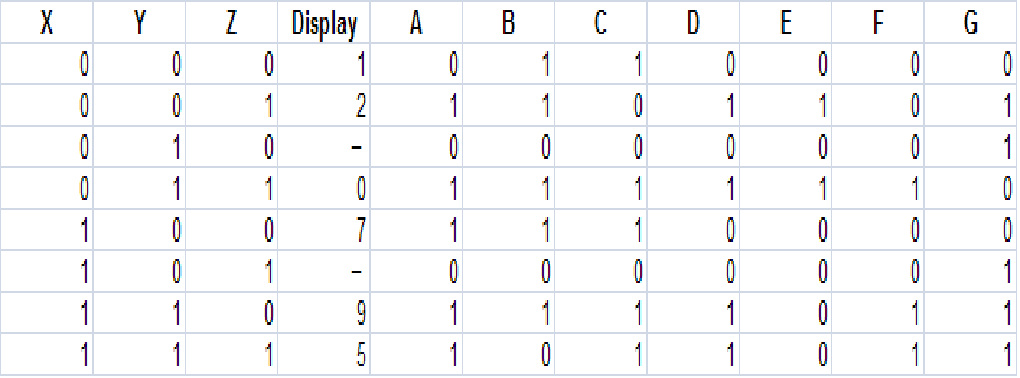
Here u can see the truth table i created which was based on my date of birth (12-07-95). This table looks a bit diffrent cause i added the X,Y,Z switches. this is what i simplified by K-mapping.
K-Mapping
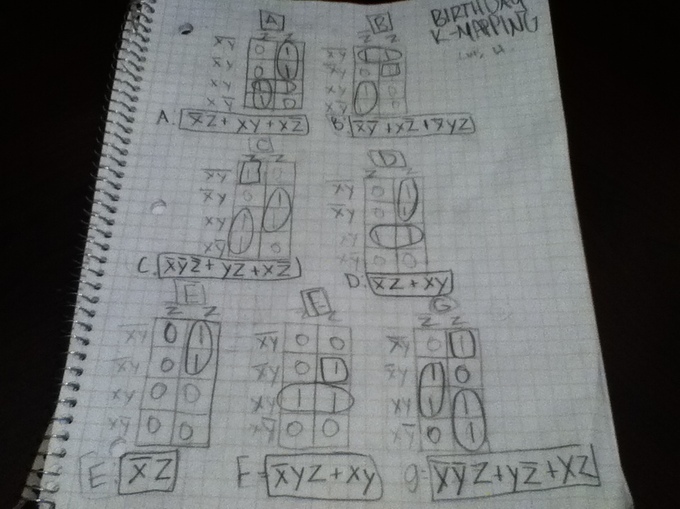
This is the K- mapping work i did based on the minterms i got in from the truth table.As you can see I had to K-map 7 diffrent minterms,one for every of the 7 segments. Here are my simplified minterms i got...
A: X'Z + XY + XZ'
B: X'Y' + XZ' + X'YZ
C: X'Y'Z' + YZ + XZ'
D: X'Z + XY
E: X'Z
F: X'YZ + XY
G: X'Y'Z + YZ' + XZ
A: X'Z + XY + XZ'
B: X'Y' + XZ' + X'YZ
C: X'Y'Z' + YZ + XZ'
D: X'Z + XY
E: X'Z
F: X'YZ + XY
G: X'Y'Z + YZ' + XZ
Birthday Drawings(AOI/NAND/NOR Implemented)
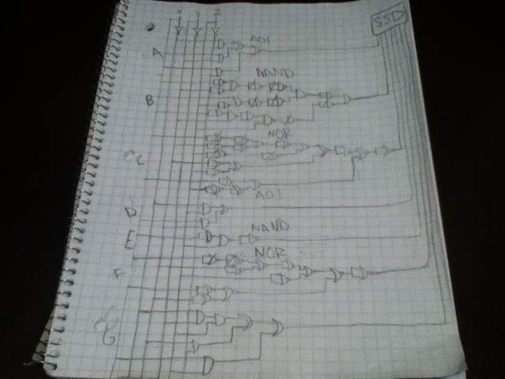
As stated on the constraints i made my drawn ciruit implimenting 2 NAND,2 NOR and the rest were AOI.some of the gates have been crossed out cause they cancle each other out.They will no be their on my final design. The circuit was based on the simplified minterms i got from K-mapping the truth table.I used all the skills that Mr. Wemp taught me this semseter to create the circuits.
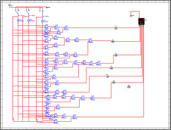
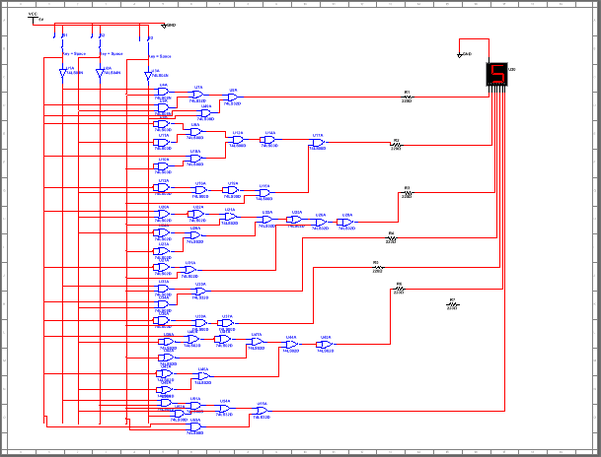
Final Design(Multisim)
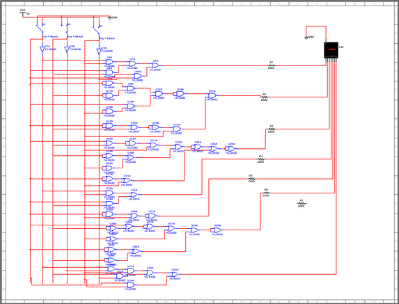
This shows the dashed segment that gose between the numbers.scince it appears twice in my birth date it can be displayed by either X'YZ' or X'YZ.
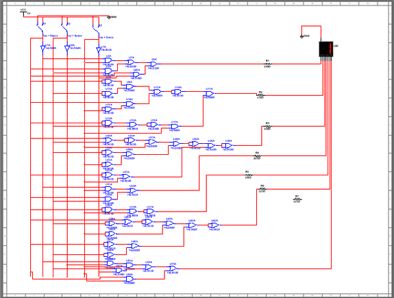
The first test shows all switches off(X'Y'Z') and the SSD displays the number 1,it matches the results on my truth table.
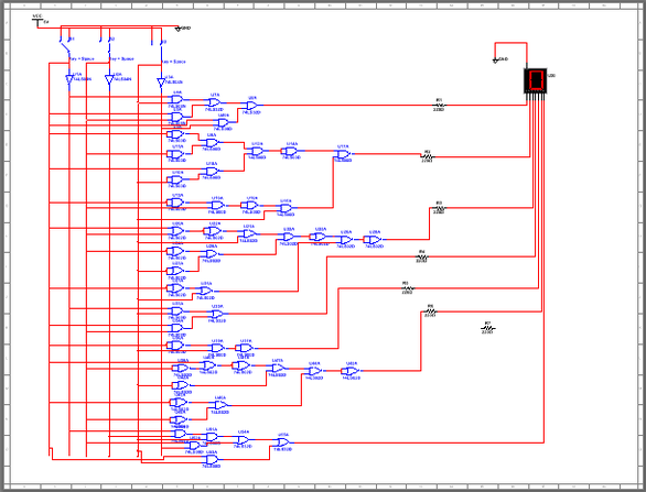
The second test shows the first two switches off and the last one on(X'Y'Z) and the SSD displays the number 2,it matches the results on my truth table.
The third test shows the first switch off and the other two off(X'YZ) and the SSD diplays the number 0,it matches the results on my truth table.
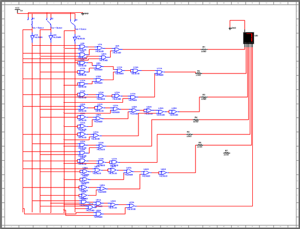
The fourth test shows the first switch on and the other two off(XY'Z') and the SSD displays the number 7,it matches the results on my truth table.
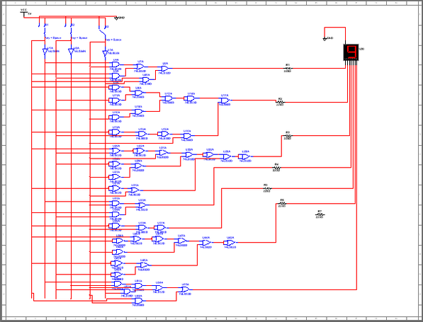
The fifth test shows the first two switches on and the last one off(XYZ') and the SSD displays the number 9,it matches the results on my truth table.
The last test shows all the switches on(XYZ) and the SSD displays the number 5,it matches the results on my truth table.
Conclusion
This project was an easy project because i learned all my stuff.When i first saw the seven segment display i thought it was gonna be confusing and hard. When i saw the chart and everything was explained I knew it would be an easy project cause i just had to apply what i learned. I think this project shows all that i have learned since the first day of the semester.
The part were i stummbled a bit was when i was drawing the circuits.When i saw the example posted on the presentation i noticed that when they did their NAND and NOR circuits they simplified it by not putting an inverter equivallent(NAND/NOR) and just using the inverted circuit line that they used for the AOI design.So when i went to do mine i tried to do the same thing but i got confused cause i think i thought about the inverted inverter thing to much.When i build my circuit the AOI part was good but my NAND and NOR circuits it didnt work cause the segments didnt light up and it frusterated me a bit but then i went back and just used the NAND and NOR inverter equivallent.I would have taken my time to go back and fix it but I was busy studding for my other finals.still it works accordinly to my birthday.
This semster i learned alot thanks to Mr. Wemp and my classmates who helped me when i needed it.I learned what minterms were and how they apply to the circuits.I learned how to get your minterms from a truth table and then I learned about Boolean and Demorgans theroms wich are used to simplify the minterm so you dont have to wire so much.This is what i had the most dificulty learning.Demorgans therome was hard but latter on I understood it better and it was pretty much just cancling out negatives.But Boolean was pretty hard cause i was so use to seeing numbers and when i saw that they were using letters instead it threw me off. It took me a while and i still have a bit of a problem with it but i pretty much get the basic concept.
My final thoughts on this project was that it was a good way of measuring how much you have learned it covers pretty much every thing that we have learned up to now. One thing that i would diffrent was to make my multisim a bit more organized. Also this was a good way on seeing what skills i had to work on before i take the actaul final test for my class.This semster was challanging but it was also interseting.I we hope we get to do more hand on projects next semester.
