Digital Game counter
digital Signal
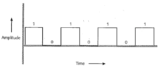
A digital signal is pretty much the opposite of a Analog signal.Its signal drops from its designated voltage to zero straight down as shown below.It pretty much means that it is either on or off.
Problem Statment
Make a design in which you use both combinational logic and sequential logic to convert digital signals into a digital die.u must come out with six diffrent
outputs.
outputs.
Constraints
- use multisim
-use AOI logic
-make the conbinational logic and sequential logic into one digital signal circuit
-use AOI logic
-make the conbinational logic and sequential logic into one digital signal circuit
Documentation
Initial Combinational Logic Design
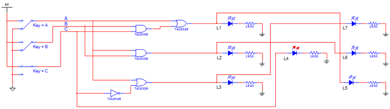
In the Combinational Logic circuit I put some probes instead of the LEDs.then i build the circuit using SPDT switches and AOI logic as shown above
Inital Sequential Logic Design
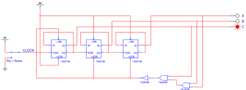
In the Sequential logic i used the SPDT switches to record the outputs.This told me wich probe lit up A,B, or C and with this information i created my truth table.
Calculations
I have to use AOI logic(AND,OR,INVERTERS)
I have to make both the sequential circuit and combinatonal circuit into one digital circuit
I have to make both the sequential circuit and combinatonal circuit into one digital circuit
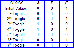
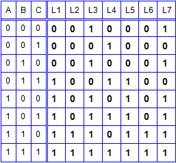
Values Table(Sequential Logic)
Truth Table(Combinational Loogic)
Final Design
The first step to making the digital game counter was to make the truth table and the value table for the combinational and sequential circuits.three "D" Flip flops in a row were required in order to create a random number generator with a number limit of six (6) . The first flip flop alternates its output every other time, the second flip flop alternates its output every second time, and the third flip flop alternates its output every fourth time. By the end a random binary number, a three digit combination of 1s and 0s, is created.
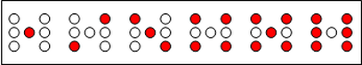
Once the flip flops generate the three digit binary number 1-6, the combinational logic portion comprised of AND, OR, and INVERTER gates translates the number to correlate with seven LEDs in a classic dice configuration. This entire process loops continuously until the electric pulse is stopped.
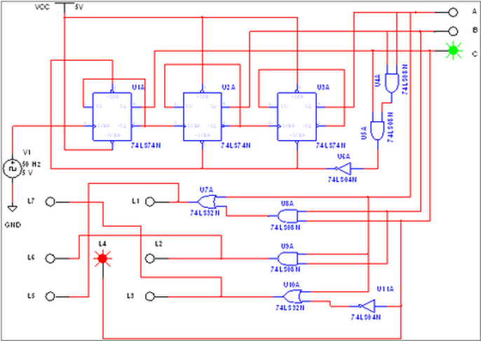
This was my final design wich contains no spdt switches and was made by combining both the sequential and combinational circuits.It sends digital signals to the flip flops(74LS4N).These flip flop switches can store memory and send it out throughout the circuit.They will work as long as they have a power source(Clock Voltage Component) and ground(GND).As u can see on the bottom these are the outputs that u must get once it is runed through Multisim.
Once the flip flops generate the three digit binary number 1-6, the combinational logic portion comprised of AND, OR, and INVERTER gates translates the number to correlate with seven LEDs in a classic dice configuration. This entire process loops continuously until the electric pulse is stopped.
This was my final design wich contains no spdt switches and was made by combining both the sequential and combinational circuits.It sends digital signals to the flip flops(74LS4N).These flip flop switches can store memory and send it out throughout the circuit.They will work as long as they have a power source(Clock Voltage Component) and ground(GND).As u can see on the bottom these are the outputs that u must get once it is runed through Multisim.
Reflection
I thought this project was pretty tough.I think that it was mainly cause i did it late and it was hard to do this and keep up with what we are doing right now.One thing that i learened from doing this project was the difreance between a digital signal and a analog signal. the main diffrence was that a digital signal is always off or on and a analog signal has a really smooth and curvy wave wich means that it is always moving and is always at diffrent levels of amps.Another thing that i learned about was the sequential logic cause i was so use to doing truth tables that when i saw that it was pretty easy to understand it once i did i figured out how to combine the circuits.I think that mabey i should have made the final design a bit less complicated to read cause at a first glance the design looks really complicated. Also if i could redo the whole semster i would turn in my projects on time so i dont jave to deal with this later when harder stuff comes.
