Fireplace Control Circuit
Problem Statement
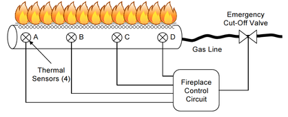
The Acme Fireplace Company has hired you to redesign the fireplace control circuit for their latest residential gas fireplace.The fireplace burner is equipped with four thermal sensors that are connected to a fireplace control circuit and the control circuit is connected to the emergency cut off valve.
For the redesign, is has been determined that the emergency cut-off value should remain open as long as three of the four sensors indicate that a flame is present. Additionally, the designers have asked you to add a second output indicator to the control circuit. This indicator will output a logic (1) when the four sensors do not all agree (i.e., not all on, or not all off). This indicator will be used by the service technician to diagnose whether a faulty sensor exists.
For the redesign, is has been determined that the emergency cut-off value should remain open as long as three of the four sensors indicate that a flame is present. Additionally, the designers have asked you to add a second output indicator to the control circuit. This indicator will output a logic (1) when the four sensors do not all agree (i.e., not all on, or not all off). This indicator will be used by the service technician to diagnose whether a faulty sensor exists.
Constraints
- The Emergency Cut Off Valve should remain open id three of the four sensors indicate that a flame is present.
-For the Faulty sensors all four sensors have to agree(either off or on)
-The Emergency Cut Off Valve circuit must be made using only NAND Implementation(Only NAND gates)
-The Faulty Sensor circuit must be made using only NOR Implementation(only NOR gates)
-For the Faulty sensors all four sensors have to agree(either off or on)
-The Emergency Cut Off Valve circuit must be made using only NAND Implementation(Only NAND gates)
-The Faulty Sensor circuit must be made using only NOR Implementation(only NOR gates)
Truth Table
This is the truth table that i made according to the problem statement.It has both the Emergency Cut Off and the Faulty Sensor results

Emergency Cut Off Valve(Unsimplified): F1=A'BCD+AB'CD+ABC'D+ABCD'+ABCD
Faulty Sensor(unsimplified): F2=A'B'C'D+A'B'CD'+A'B'CD+A'BC'D'+A'BC'D+A'BCD'+A'BCD+AB'C'D'+AB'C'D+AB'CD'+ABC'D'+ABC'D+ABCD'
Faulty Sensor(unsimplified): F2=A'B'C'D+A'B'CD'+A'B'CD+A'BC'D'+A'BC'D+A'BCD'+A'BCD+AB'C'D'+AB'C'D+AB'CD'+ABC'D'+ABC'D+ABCD'
K-mapping
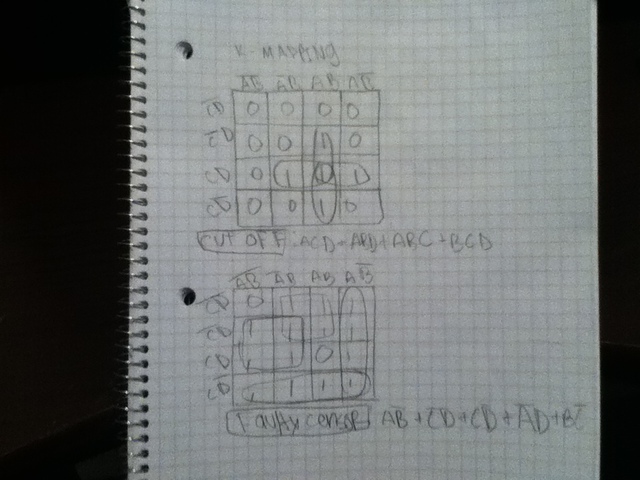
After K-mapping i got these simplified logic expresions
Emergency Cut Off Valve(simplified):ACD+ABD+ABC+BCD
Faulty Sensor(simplified)AC'+BC'+A'D+AB'
Faulty Sensor(simplified)AC'+BC'+A'D+AB'
NAND(Cut-off)NOR(Faulty Sensor) Drawings
Unsimplified
After I had gotten my simplified logic expressions for the Emergency Cut Off Valve and the Faulty Sensor I started to draw the circuits.This is the unsimplified version of the Emergency Cut Off Valve(top) and the Faulty Sensor(bottom) circuits wich i used the conversion sheets from a AOI to NAND/NOR to make.

Simplified
After I got my unsimplified version of the Emergency Cut Off Valve and Faulty Sensor circuits, i simplified it by crossing out the not-nots(inverted inverters) cause they cancle each other out so they are just useless and would make the design more expensive to make.

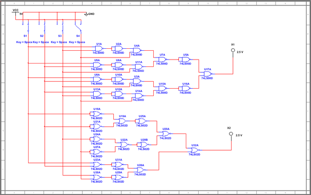
Multisim
After I had drawn the circuit it was time to test it out.I used Multisim to make a copy of my design and tested if it worked.It matched the truth table results and all i had left to do was to bread board it.
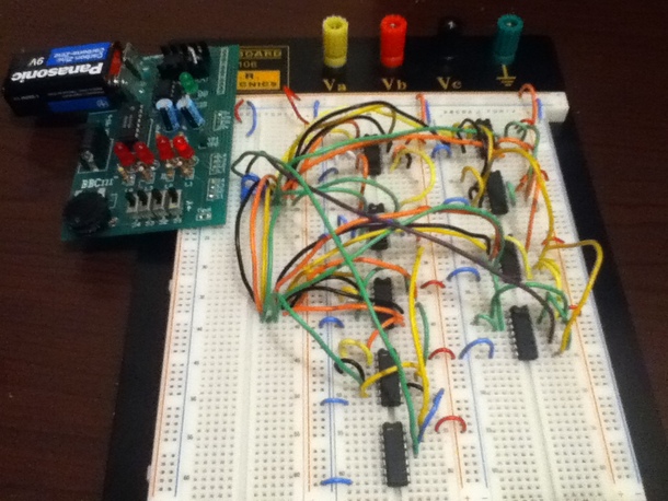
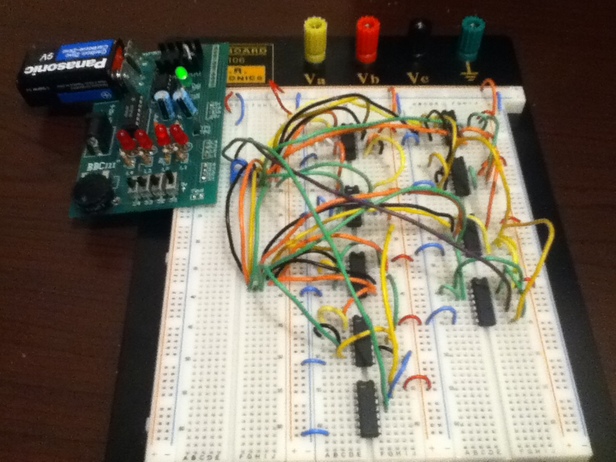
Breadbording
This is the final breadboarded design, it works accordingly to the truth table.The gates on the left column make up the emergency cut-off circuit and it was made from only NAND gates.The gates on the left column make up the faulty sensor circuit.It was made from only NOR gates.
Tests
On the first test all the switches are on(ABCD)only the Emergency Cut Off Valve LED is turned on and the faulty sensor LED is turned off as stated on the truth table.
On the second test when the first three switches are turned off and the last one is on(A'B'C'D) the Emergency Cut Off LED is turned off and the Faulty Sensor LED is on as stated on the truth table.
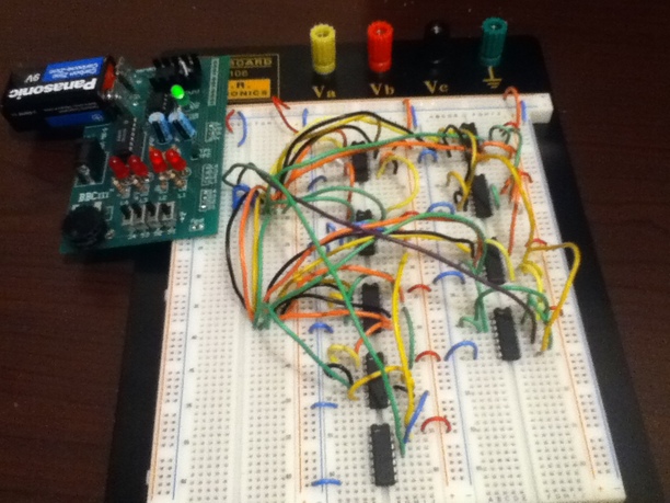
On the thrid test when the first three switches are on (ABCD') both the Emrgency Cut-Off Valve LED and the Faulty Sensor LED are on. As it states on the truth table when any three switches are on both LEDs will turn on
Conclusion
Well my final thoughts on this project was that it was a bit more challenging.We got to solve the K-Mapping by ourselves and it made me understand it more.Another part that was pretty challenging was when i had to simplify my drawn circuit it wasnt just crossing out random gates.You actually had to think and see how it would effect the final logic expression.The hardest part for me was the breadboarding.I thought i could do it quick so i did but then the inputs didnt match the truth table.Once i looked over it a couple of times i found 4 or 5 wires that were put in the wrong inputs after fixing it everything worked out.
What I learned from this project was to work at a slower pace cause when u work to fast it is easier to make mistakes.For example when i made the circuit drawings i missed out a part of the logic expression.It was a good thing that i caught the mistake in the early stages of my design cause it would have sucked to have to find the problem later on.I also learned that when i work on my protfolios at home it makes the work i have to do in class less and i can catch up with the current things were learning about.
One thing that I would have done differnt in this project was to make the logic expression as simplified as possible.Although I had gotten the Emergency Cut Off Valve simplified down to only 17 NAND gates I later found out that one of my class mates was able to simplify it even more down to 12 gates I was pretty impressed that it worked the same and that he was able to simplify it more cause in a real world situation he would have gotten hired to make the design for the fireplace instead of me cause his design would have been more cost efficent.Overall it was a pretty intresting project and it made me learn alot.
