MSI 4-Bit Counter
Problem Statment
In this activity we will simulate and analyze a 4-Bit asynchronous counter using a 74LS93 4-Bit Counter.you will create a counter that will count from
0-9 according to the design given.After that you must modify the circuit to have a count limit from 0-9, then the SSD must disply a,b,c and then reset. After that you must enter another ciruit that is given to you and figure out how it works.
0-9 according to the design given.After that you must modify the circuit to have a count limit from 0-9, then the SSD must disply a,b,c and then reset. After that you must enter another ciruit that is given to you and figure out how it works.
Constraints
-Build the circuits using the IC 74LS93
- Create a 0-9 counter
-Modify to count to C
- Build the other circut that implements SPDTs
- Create a 0-9 counter
-Modify to count to C
- Build the other circut that implements SPDTs
Calculations
74LS93 MSI IC

This is a 74LS93 IC. It has two inputs, two resets, and four outputs to a hex display.The IC has four flip flops inside of it. The picture above shows that the IC has four flip flops compressed inside of it. This chip has the first flip flop is by itself which is a big advantage cause it makes the chip really flexible cause you can use the chip as a single flip flop. Also if you want to use all the flip flop you can all you have to do is wire the first flip flops Q to the second flip flops Clock, this will create a 4 bit divide by two counter that can count up to 16 in binary. I think that the circuits we will do will use the 4 Bit and modify them to count different counts.
4- Bit Binary Up Counter(0-9)
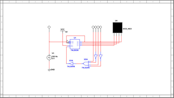
This is the circuit that was given to us.It is a 4-Bit binary counter. As I said above the IC 74LS93 is a compression of four D- Flip flops so imagne a 3-Bit counter with another flip flop but all of the wring is put into the 74LS93. If the inputs to the NAND had no inverters it would count to,0000 be inverted to 1111 and add up to 15. This would display, a 14 in the HEX Display and then restart. By putting inverters in the 2^1s binary position and 2^3s binary positon the circuit will only reach 1010 and be inverted which is 0101.The binary count will add up to 10 which will display a 9 on the HEX and this 9 is fhow the circuit works.
This is the 4- Bit Binary Up Counter simulation which works as expected.As you can see it counts to 9 and then resets to 0.
4- Bit Binary Up Counter(C Count Limit)
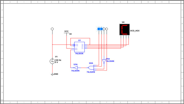
After i made the 4-Bit Binary Up Counter we had to modify it to counter to count from 0 to C and then reset. So what you see in my design is one inverter in the 2^3s place that goes into the 4 -input NAND gate. By doing this you get the maximum output of 0011 from the NAND gate.Then the invrter switches the binary number to 1100 which equals 12. As you know the HEX Display only counts to 9 and after that the alphabet starts at the 10s place with A so we B is 11 and c is 12 which is what is displayed on my circuit.
This is the 4-Bit Binary Up counter simulation that counts to C and then reset.Every thing works according to my design.
4-Bit Binary Up Counter with SPDTs
First of all I must explain that the snag it tool on the computer did not let me toogle any of the SPDTs while it was recording, so the first picture below the video show what would happen if the first SPDT is toggled and the second picture below the video shows what would happen if the second SPDT is toggled.
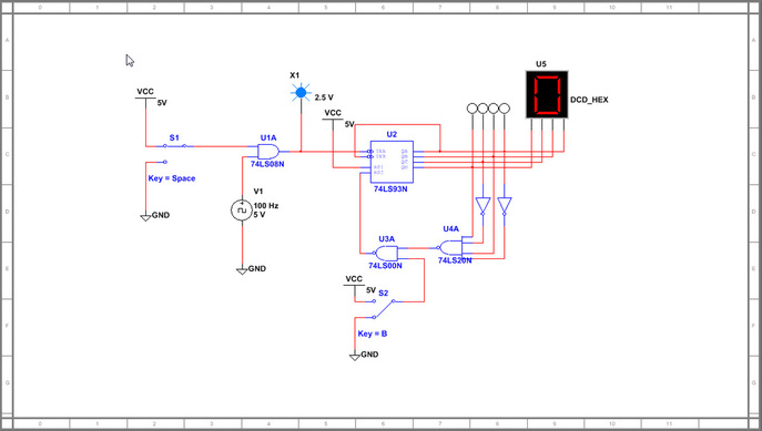
This is the modified 4-Bit MSI counter. The first SPDT makes the count be held which means that it will keep a number on the HEX display constant while the simulation is running. The second SPDT makes the count stop automatically and reset to 0 reguardless of what # is on the HEX Display. The way this works is that whenever the clock pulse was stopped or removed (when the 1st SPDT was toggled to GND) then the counter just held its spot. If it was on 9 (as shown on my 2nd when the switch moved to ground, then it would stay there until the switch was moved back to 5V (or VCC). When the second SPDT was switched, then the counter would reset back to zero and stay there until the switch was moved back to 5V.
1st SPDT toggled to GND

When the 1st SPDT is toggled to GND it makes the count remain at the current number
2nd SPDT Toggled to GND
When the 2nd SPDT is toggled to GND it cause all the flip flops to reset which makes the HEX display reset back to zero
Reflection
What I learned from this project was how progression in the digital world, usually has to do with making things smaller but them having the same if not a better function than before. In this case the 74LS93 IC compresses four flip flops into one chips and their are so many benefits to this chip as I described in my calculations. Medium Scale is pretty much the same as small scale the only difference is that we use compressed flip flop chips. The only time I kind of didn't get it was when I had to make the counter count to C I could get it to count to C but when it came down to explaining why I couldn't do it. I use to think that A started in the 11s place but I was later corrected and I found out that the Hex Display counts from 9 and then goes on to A(in the tens place and then all the way to F. I think I got how the SPDTs work on my last circuit and I think this will help me figure out how to make the 60 sec. counter stop which is the project that I am doing right now.
