MSI Synchronous Counters
74LS163
Problem Statement
Use the 74LS163 to create a 2-9 Binary up counter. Test and simulate the circuit and verify it works as expected .After you have made the circuit modify the circuit to count from 4-14(E).Test and simulate the circuit and verify it works as expected.
Constraints
-Use the 74LS163
-Create the circuits in Multisim
-Breadboard at least one of the circuits
-Record data
-Create the circuits in Multisim
-Breadboard at least one of the circuits
-Record data
Calculations
The 74LS163 is a IC chip that has four synchronous counters in it so its maximum count is 15 (E). As we learned the has a input called a load and it is loaded with a binary count from the ABCD Inputs. Every time the load gets a 1 it restarts the count at the number that it was given from ABCD. By putting inverters on the Q inputs you can control the maximum count depending on where they are placed. The IC also has ENT and EMP inputs and for the projects we are doing they will be wired to VCC so they wont change nothing. A disadvantage about the IC is that it only counts up cause u cant change the parts in the inside of the IC.
Documentation
2-to-9 Binary Up Counter (163)
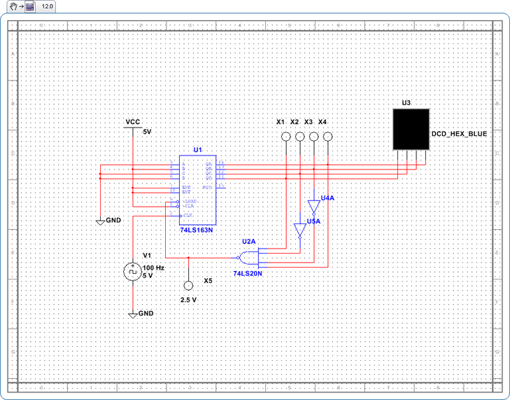
This is the 2-to-9 Binary Up Counter. The way it works is pretty simple. So as you can see the inputs A,C, and D are wired to GND which is 0 and B wired to 1 which is in the 2^1.This will make the count restart at 2.To make the count end at 9 I had to place 2 inverters on Q1 and Q2, this made the maximum count be 1001.It then gets inverted to 0110 by the NAND gate and then again to 1001 by the load input which in binary count is 2^0 +2^3 and this will make the max count be 9.
2-to-9 Binary Up Counter Video (163)
This is the video of the 2-to-9 Binary Up Counter. It works as expected and makes the counter restart at 2 and restart at 9.The probes show the binary count that go into the HEX Display.
2-to-9 Binary Up Counter with 74LS163 (bread boarded)
This is the 2-to-9 Binary Up Counter(74LS163).It has been bread boarded based on the Multisim design. The only difference is that I had to put a SS display instead of the HEX display cause its not real. I put a 74LS47 encoder to make the SSD work.
Please note that I made a mistake in the video and said the circuit uses a 193 but it actually uses a 74LS163 IC.
Please note that I made a mistake in the video and said the circuit uses a 193 but it actually uses a 74LS163 IC.
4-to-14 Binary Up Counter (163)
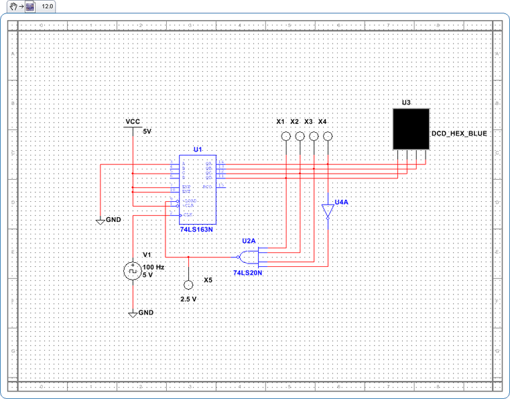
This is the 4-to-14 Binary Up Counter that I had to make by modifying the 2-9 counter. It was actually very easy to modify the count once I got the concept of the MSI counter. A,B, and D are all 0 and C is to 1 which is 2^2 and this equals 4 which is the number that the counter restarts at. To make the maximum count be 14 I put a inverter on Q0. This means the binary count will be 2^1, 2^2, and 2^3 and when you add the numbers 2+4+8 it will equal 14 which is the number at which the counter ends at.
4-to-14 Binary Up Video Counter (163)
This is the 4-to-14 Binary Up Counter Video. It works according to the design and the probes show the binary count that goes into the HEX display.
Conclusion
1. What are the advantages of implementing a synchronous counter with the 74LS163 integrated circuit versus using discrete flip-flops and gates?
An advantage of using the 74LS163 IC over using discrete flip flops and gates is that every thing is dramatically simplified. To change where the count restarts you change ABCD inputs and to change the max count you change Q0,Q1,Q2, and Q3 outputs.
2. Are there any disadvantages to using the 74LS163 integrated circuit?
The biggest disadvantage of the 74LS163 is that it can only count up as I stated above. This is cause it only has a clock that counts up and since the MSI chip is synchronous you can not make it count down.
3. Analyze the counter shown below to determine the counter’s lower and upper count limit.
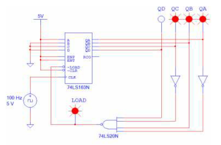
The 74LS163 counter has A wired to VCC and BC and D are wired to GND. This gives us the binary number of 1000 so the count will start at 1.Q0 and Q2 have inverters on them so the maximum binary count will be 0101 and 2^1=2 and 2^3=8.The max count will be 9 cause 1+8 is 9.
74LS193
Problem Statement
Build a 13-to-16 Binary Down Counter using the 74LS163 IC chip. Using what you have learned from the chip, modify the circuit to count down.
Constraints
- Build the circuit using the 74LS193 IC
- Use Multisim
- Use a 74LS20,74LS04 and any other gates required
- Record data
- Use Multisim
- Use a 74LS20,74LS04 and any other gates required
- Record data
Calculations
The 74LS193 is an improved version of the 74LS163 chip. The thing that makes it so much better than the 163 is that the193 chip has the capacity to count both up and down. The reason it can count is that the Chip has a Up and Down input and depending on which input u put it, is how the clock will count. When making the chip count down we will have to reverse the functions of ABCD and Q0Q1Q2Q3.Another thing that we learned from this lesson is that the 74LS193 has an asynchronous load and what this means is that a when the clock counts up it takes a number away from the maximum count and when it counts down it adds a number to the restart count.
Documentation
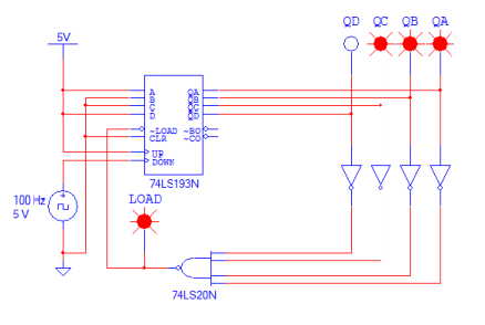
13-to-6 Binary-Down Counter (193)
This is the 13-to-6 Binary Down Counter, It counts down from 13-to-6.First of all note that the clock is wired to the down counting input, this means that the functions of ABCD and Q0Q1Q2Q3 will switch. To make the counter start at 13(D) we wired AB and D inputs to VCC and B to GND. This means that we get the binary count of 2^0,2^2 and 2^4 and 1+4+8= 13 which is the number we want to start at. The inputs Q1 and Q3 have inverters on them so the count should restart at 5 cause 2^0 and 2^2 equals 5. But as we learned from the lesson the 74LS has a Asynchronous load which means that when it counts down it adds a number so instead of having the count restarts at 5 it restarts at 6.
13-to-6 Binary Down Counter Video (193)
This is a Video of the 13-to-6 Binary Down Counter with a 74LS193 IC. It works as expected and the probes show the binary count that is fed into the HEX display.
6-to-13 Binary Up Counter (193)
This is the 6-to-13 Binary Up Counter that has a 74LS193.The first thing we had to modify from the previous counter was to wire the clock to the up count input of the 74LS193.This means that the functions of the inputs ABCD and Q0Q1Q2Q3 are reversed back to normal. ABC & D will control where the count will restarts and Q0Q1Q2Q3 will control the maximum count. Another thing that changes when the 74LS193 counts up is that the Asynchronous Load takes away a number from the HEX display instead of adding one. To make the count restart at six I wired the inputs B & C to VCC and A & D to GND. This means that we get the binary count of 2^1 and 2^2 which equals 6 which is at the number that the counter restarts at. To make the number end at 13 we had to change the Q outputs. As I stated above the Asynchronous load will delay the pulse by one so I put an inverter on Q0.This means we get the binary count 2^1, 2^2, and 2^3 which is 2+4+8 and this equals 14.The Asynchronous load subtracts a number which makes the maximum count 13.
6-to-13 Binary Up Counter Vid (193)
This is the video of the 6-to-13 Binary Up Counter. It works according to what we learned and the probes show the binary count that are going into the HEX display.
Conclusion
1. What are the advantages of implementing a synchronous counter with 74LS193 IC over the 74LS163 IC?
The biggest advantage of the 74LS193 is that it has the ability to count both up and down unlike the 74LS163 that can only count up. The 74LS193 is obviously the best choice cause its flexibility.
2. What is the difference between a synchronous load input(i.e., 74LS163) and an asynchronous load input(i.e., 74LS193)?
Their is a big difference between a synchronous and asynchronous load inputs. The Synchronous load is synchronous and this means that the count from the Q outputs will stay the same when it goes through the load input. When you put inverters on the Q outputs the circuit will change as expected. The Asynchronous load input is different. Since it is asynchronous it delays the counters pulse by one when it counts up, it adds 1 to the pulse when it counts down. This means that it will either add or subtract 1 to the restart/maximum binary count. For Example on the 6-to-13 up counter you see the inverter on Q0 and you would calculate the maximum count would be on 14(E) but since the pulse goes through the asynchronous input and it is counting up, it subtracts a 1 from 14 and this is why the count ends at 13.
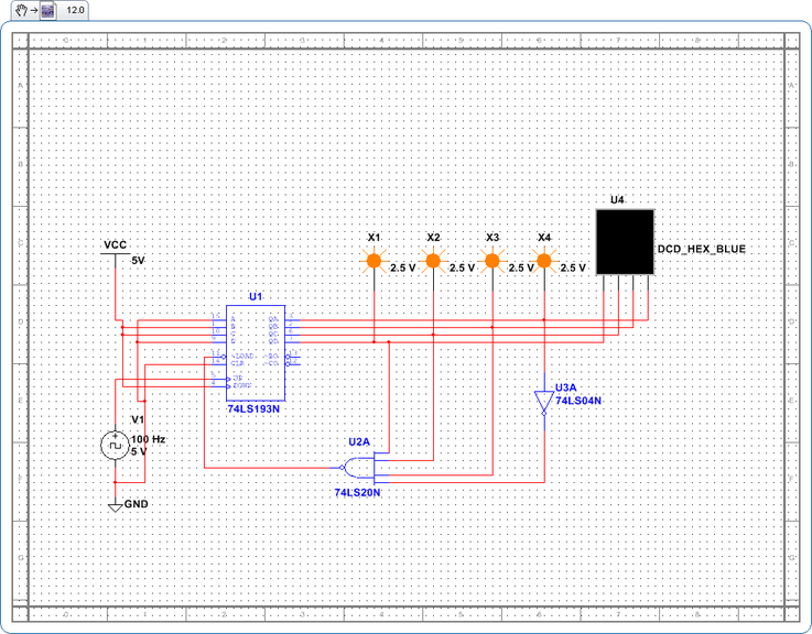
3. Analyze the counter shown below to determine the counters lower and upper count limit. Explain how you know this?
The biggest advantage of the 74LS193 is that it has the ability to count both up and down unlike the 74LS163 that can only count up. The 74LS193 is obviously the best choice cause its flexibility.
2. What is the difference between a synchronous load input(i.e., 74LS163) and an asynchronous load input(i.e., 74LS193)?
Their is a big difference between a synchronous and asynchronous load inputs. The Synchronous load is synchronous and this means that the count from the Q outputs will stay the same when it goes through the load input. When you put inverters on the Q outputs the circuit will change as expected. The Asynchronous load input is different. Since it is asynchronous it delays the counters pulse by one when it counts up, it adds 1 to the pulse when it counts down. This means that it will either add or subtract 1 to the restart/maximum binary count. For Example on the 6-to-13 up counter you see the inverter on Q0 and you would calculate the maximum count would be on 14(E) but since the pulse goes through the asynchronous input and it is counting up, it subtracts a 1 from 14 and this is why the count ends at 13.
3. Analyze the counter shown below to determine the counters lower and upper count limit. Explain how you know this?
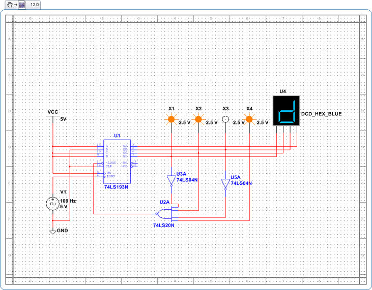
The clock is counting down, so ABC and D will control the maximum count and outputs Q0Q1Q2 and Q3 will control the number that the counter restarts at. A and D are wired to VCC and B and C are wired to 0 and this give us the binary number 1001 which means the count will end at 9. Q0,Q1,2 and Q3 are all inverted so the count would restart at 0 but since it goes through a asynchronous load and it is counting down you must add a 1 so the count will restart at 1.
