SSI Asynchronous Counters
Problem Statement
Using Multisim create a 3- Bit up counter made from D, and JK flip flops to count from 0-7. After analyzing the circuit, use what u have learned from the flip flops lesson and apply that to turn the counters into 3-Bit down counters which count from 7-0.
Constraints
- Make 3-Bit up counters using only 74LS74(D) and 74LS76(JK) flip flops
- Use HEX display to display values
-Make the 3-Bits into down counters(7-0)
-Explain what the ripple effect is
- Use HEX display to display values
-Make the 3-Bits into down counters(7-0)
-Explain what the ripple effect is
3-Bit Counting(0-7)
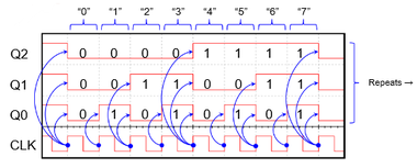
Since we are going to count from 0-7 we need to use a 3- bit register.The reason for this is that a 3 bit counter has a counting limit of 8 digits(0-7).when the clock pulse passes through a flip flop(D or JK) the pulse is split in half. when we wire this to the HEX display it reads the three inputs from Q or Q' in binary counting.It adds the numbers and displays the output. For example when the Hex display gets the inputs,1,1,0 it displays a 0 cause the first number,0 has no value so it turns into to a zero , the second number 1 is in the power of 1s place so it makes 2 be powered by 1 which is 2.the third number 1 is in the power of 2s place so two is powered by 2 which is 4. When you add the three values 0,2,4 you get 6.So a 3-bits max is 3 ones, and 111 equals 7(as shown on the diagram below) and then it repeats itself which is what we are looking for.
Documentation
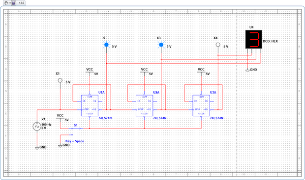
3-Bit Up Counter(D-Flip Flops)
This is the 3-bit up counter I made outta D-flip flops. The 3 probes on top of the picture below show the binary numbers that go into the HEX display, note that the numbers read from right to left cause the flip flops half the pulse from right to left so the chart I showed u above is pretty much flipped.the probe that is connected to the clock wire shows the pulse of the clock. The circuit also has a SPDT that switches from VCC and GND which is wired to clear. When Both of our asynchronous inputs are wired to VCC they do not affect the circuit. When the SPDT is switched to GND, clear turns to 0 and when preset is 1 and clear is 0,both Q and Q' outputs turn to zero and the pulse is cut. So as I stated above when the clock pulse goes through a flip flop the pulse is cut in half and made longer. By connecting the HEX display to the Q outputs it can get the necessary binary numbers to create the number it is going to display and since we connected it to Q the pulse starts at all 0s and goes up to 7.

3-Bit Down Counter(D-Flip Flops)
Below is 3-bit down counter. We had to modify the up counter that I showed you above so that it would count down instead of up. In order to do this I had to use what I had learned from the flip flops lesson. since a down counter is the opposite of an up counter it must read the opposite numbers that Q outputs. Q' is exactly that, Q not, so all I did was wire the hex display to Q' and it worked exactly how I predicted.
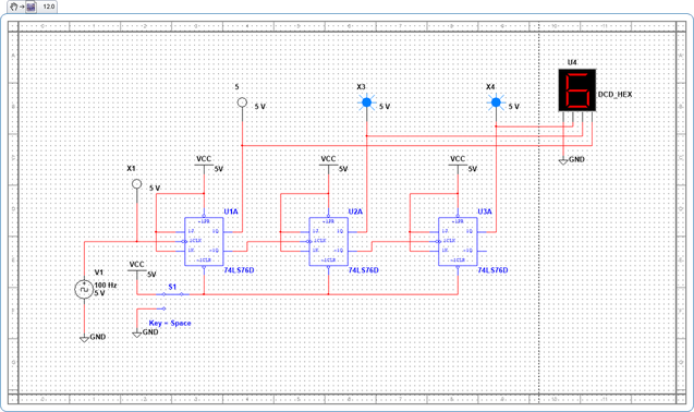
3-Bit Down Counter(JK-Flip Flop)
Unlike the D flip flop version of the 3- bit flip flop, we were told to make the down counter first for the JK flip flops. It is pretty much the same thing as the D flip flop except we had to wire JK flip flops instead of Ds. When J and K inputs are wired to 1 it causes the Q out put to toggle, or be the opposite. This creates the same divide by two pulse transition that we get from the D flip flops. The difference is that when we wire the hex display to Q it counts down the reason for this is that since we are using JK flip flops the initial pulse is toggled so it flips the numbers around, hence the pulse is flipped and counts down. Below the probes show the binary number 011, which equals 6 as shown on the hex display , note that probes read from right to left and not from left to right like the D counters.
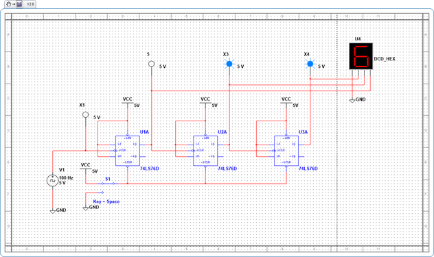
3-Bit Up Counter(JK-Flip Flop)
This is the 3-bit up counter. It is the modified version of the JK down counter and it counts from 0-7. It was a bit harder to figure this out but when I really thought about the JK flip flops output I got it. When J and K are 1 it toggles(makes opposite) Q so by connecting Q( which is the opposite) to the clock input it is toggled again. This pretty much makes the outputs flip around which makes the counting switch from counting down to counting up. Below you can see how the circuit was wired
The Ripple Effect
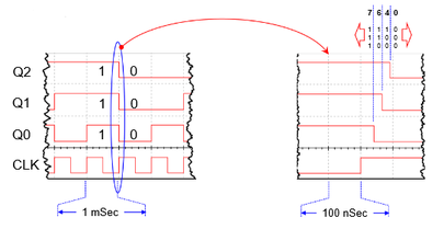
The ripple effect is the delay between the outputs of register. When you make a bit counter the output of one flip flop must go into another, pass through the flip flop and pass through the inputs(like clear, and preset),Although the pulse goes through really fast their is a delay at Nano second scale and as the delay for every count stacks up it causes a longer delay time. This causes the Q outputs to change at different times, resulting in the counter briefly producing incorrect counts. For example, as a 3-bit ripple counter counts from 7 to 0, it will briefly output the count 6 and 4 as shown above.
